2g FWD fuel tank design
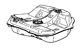
2g DSMs came from the factory with two styles of fuel tank, depending on the rear chassis configuration. DSMs with front-wheel drive did not need any clearance for a driveshaft, so they were fitted with a simple tank with a single compartment, with the pump fed by gravity. Returned fuel can be delivered to an arbitrary location, since all fuel eventually makes it's way to the fuel pump sock at the bottom of the tank on the passenger side of the car.
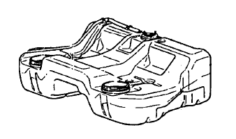
The 2g all-wheel drive DSM, on the other hand, needed allowances made in the chassis structure for the driveshaft. The result was a fuel tank that "straddles" the bump in the middle of the chassis, in a saddlebag style. This tank presented a unique challenge to the fuel system engineer: taking advantage of the fuel storage space made available on both sides, while making sure that the tank never ended up empty because one side of the "saddlebags" was full while the other was empty.
Before talking about their solution, a discussion of how the fuel system works in general is needed. The first obvious component is the fuel tank; there is a fitting on the side of the car with a tube to the rear of the tank, allowing the operator to fill it. Also attached to the tank is the fuel sending unit; on a DSM, this assembly has the fuel pump attached to it, along with piping for both the fuel pumped out of the tank and for unused fuel returned to the tank. The pump has a sock attached to it which rests at the lowest part of the tank; this sock serves as a pick-up for the fuel pump.
The pump sucks fuel through the sock and pushes it through a set of piping (the "feed" line) under the car to the engine bay, where it terminates at the bottom of the fuel filter; on DSMs, this is mounted on the firewall just below the battery. From the top of the fuel filter, a line runs to the fuel rail (positioned at the top of the engine, between the intake manifold and the head). The fuel rail is the attachment point for the four fuel injectors (which spray fuel directly into the cylinder head), and the fuel pressure regulator (FPR).
The sole purpose of the fuel pressure regulator is to maintain a constant pressure in the fuel lines so that the fuel injectors behave consistantly. To do this, it matches the air pressure in the intake manifold to the fuel pressure in the rail; with the engine off, it maintains a base fuel pressure of 43 psi (37 psi on a 1g DSM), and as boost increases, the regulator increases pressure in the fuel rail to match it, in a 1-to-1 manner (ie. if there is 17 psi of manifold pressure, fuel pressure will be 60 psi). The way that the FPR accomplishes this is in concert with the fuel pump; the pump pushes as much fuel as it can at it's current voltage level, and the FPR lowers that pressure by allowing fuel to exit the rail past it, and into the "return" line back to the fuel sending unit in the tank.
On a 2g FWD DSM, the return system is very straightforward; it simply dumps the excess fuel back in the fuel tank, without much fanfare. On a 2g AWD, however, the system is a bit more involved. The return line enters the tank at the sending unit, much like on a FWD, but the fuel doesn't go directly into the tank. Instead, there is a chamber with a small hole in the bottom of it, which has both the return line connected to it, and a "suction" line which exits the tank (also through the top of the sending unit) and connects to a similar unit in the top of the driver-side saddlebag. Because of pressure differences, the returned fuel actually travels through this course, dumping into the driver's side of the tank. When fuel levels on the passenger side are lower than the small hole in the return line assembly, air pressure in the tank causes a siphoning effect, which draws fuel through the "suction" line between the two saddlebags, and actually moves the fuel from one side to the other.
The aftermarket presents a large number of opportunities for increasing the capacity of the DSM fuel system. The first obvious targets are the pump and injectors (fuel and engine management are beyond the scope of this document; the reader should, however, be aware that changes to fuel delivery should always be accompanied by appropriate programming or electronics changes).
For the pump, there are a number of changes available. The first and easiest change to supply a bit of additional fuel is to simply rewire it; the stock wiring doesn't supply more than about 11.8V to the pump, when it operates much better at a steady level closer to 14V. Stepping beyond that, the typical upgrade path is to replace the pump with a higher-flowing unit. Common replacement in-tank pumps are Walbro 190lph and 255lph offerings (the latter being available in a low- and high-pressure version), a Denso pump commonly used as the OEM pump for Toyota Supras. The stock injectors flow approximately 450cc/min of fuel each; common upgrades can bump them up in flow all the way to 1600cc/min.
These are the most crucial upgrades in the system, but they have an affect on the other components. First and foremost is the fuel pressure regulator; the factory unit is not capable of releasing enough fuel when line pressures rise higher than those provided by a Walbro 255HP at low RPMs (ie. when the largest amount of fuel is returned to the tank). Thus, when installing a higher-output pump, the FPR generally needs to be upgraded. This can be accomplished with either a "bolt-on" replacement, or with a generic rising-rate adjustable FPR which connects to the fuel rail via new lines and adapters.
Another common upgrade is to replace the factory feed and return lines with larger-diameter hose (usually braided stainless steel line), to accomodate a larger volume of fuel delivery. With a -6AN feed upgrade (and reusing the factory feed line as a return line), this is very simple and well-documented. However, should the modifier wish to replace the fittings on the sending unit with larger ones, care must be taken. In a FWD application, this is a simple matter using bulkhead fittings and a bit of cutting/drilling. The AWD saddlebag design, however, almost requires that any modification of the system replicate the functionality of the siphon effect used to equalize fuel levels on each side. This upgrade often involves either replacing the fuel rail with one which has native ports for the lines in use, or using adapter fittings for the OEM rail.
Finally, the entire tank can be replaced with an aftermarket fuel cell, which allows one to use much larger-capacity gravity-fed pumps, and in the case of the AWD fuel tank, avoid the "saddlebag" engineering problem entirely.